Great beauty and technical inventiveness represent distinctive qualities allowing an architectural work to become an icon, an emblematic figure, destined to endure across the centuries leaving an indelible trace in the society.
With their unique style, large infrastructures have always exerted a magnetic charm on the humankind. Their iconic and unmistakable forms have entered the collective imagination through hundreds of films and photographs, becoming the symbol of cities and nations.
However, behind every great work there is always a great story, and many questions with it. What are the elements composing it? How are they made? And what are the technical steps allowing the structure to last over time?
Maeg opens the doors of its offices and factories, showing the stages marking the production cycle of its projects: welcome behind the scenes of the Maeg’s world, where technique and passion come together to give life to works destined to last over the time.
The design process bases on standards, calculations, technical specifications, and drawings to define every detail of the structure in terms of production and installation.
1.1 Analysis of the documentation
The design process starts with the analysis of the project information received from the Client.
The design could be a preliminary project - providing the significant characteristics to be further developed in detail - or it could be an executive project, already including the structure’s specifications in terms of materials, dimensions, and geometric features.
An essential part of the documentation is represented by the technical specifications, namely the regulatory references to identify the requirements of the project in terms of quality, surface treatment and execution class.
1.2 Development for the production
The project is modeled and analyzed in every detail to develop the shop drawings.
Every specific detail such as geometry, holes, thickness, chamfers, welds, and quantities of pieces to produce are defined for each element of the structure, which is then labelled with an identification number (marking).
Once every single element of the structure is defined, from the shop drawings is extracted the bill of quantities, a list summarizing the required quantities, the quality, and the dimensions of the materials to be supplied for the project.
For each single plate is elaborated its construction drawing, reporting all the information on the material production processes to start the actual production phase.
1.3 Development for the construction site
After all single smallest elements composing the structure have been examined, allowing the production to start, an assembly plan is developed to establish the methods and sequence for joining these single elements into marks or combined elements, taking into account size, constructability, transportability, site layout and space, crane lifting capacity and assembly on site.
In the first place, considering the different variables, a calculation model is created to verify the structural strength of the work during the different construction phases.
Step by step, the temporary equipment necessary during the installation phase gets defined (benches, temporary towers, etc. for which executive drawings and designated calculation reports are created, in order to proceed with their fabrication), as well as the necessary lifting and transport means (cranes, barges, etc. to be supplied).
Once the methods for installation on construction site are defined, the technical office compiles a method of statement to illustrate each different stage, ensuring compliance with safety regulations.
PROCUREMENT
Commercial process providing the necessary supplies to satisfy the procurement needs of the project, basing on the bill of quantities developed by the technical office.
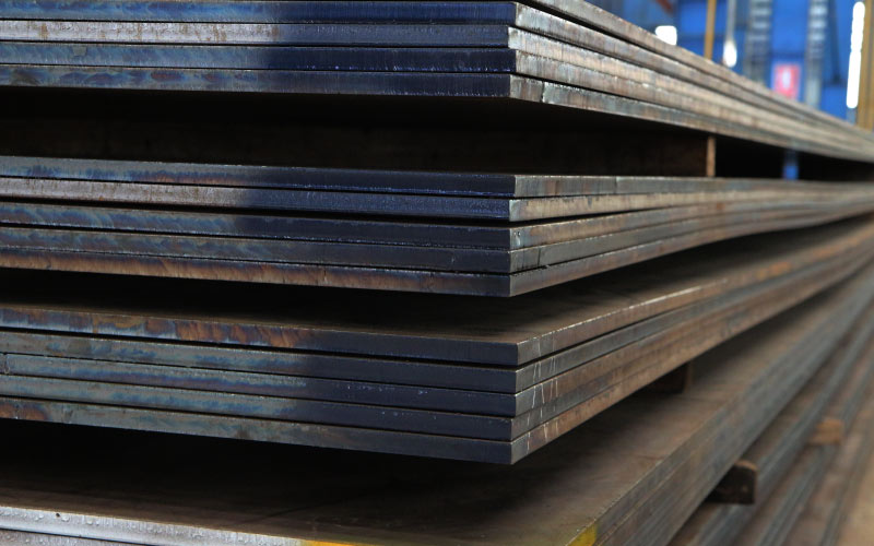
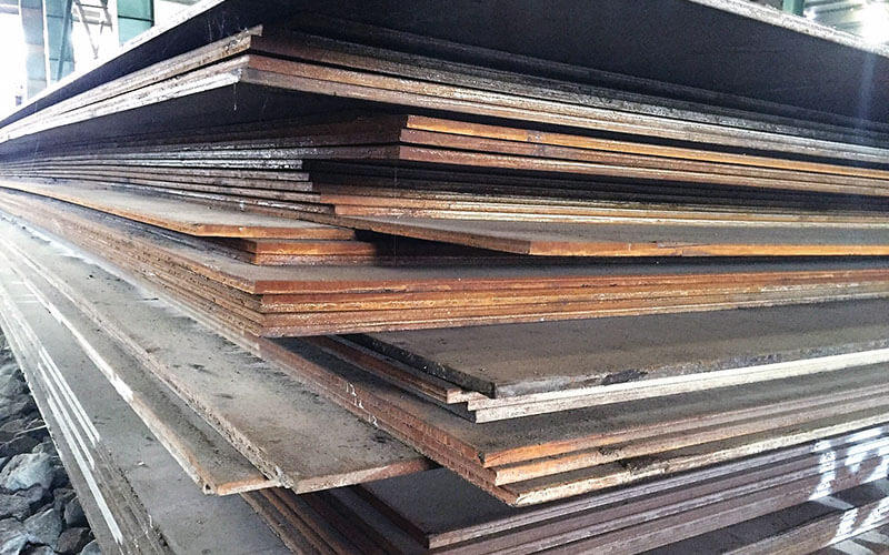
METAL SHEETS
Steel plates are cut out from metal sheets produced through rolling (semi-finished casting product made by continuous casting of liquid metal in specific shapes), a metal forming process in which metal stock is passed through one or more pairs of rolls to reduce the thickness and to make the thickness uniform.
PROFILES
Profiles are hot-rolled products called “commercial” as they follow precise international standards regarding the shape of the section.
The most common sections are:
"Double T" shaped profiles: profiles composed of two parallel flanges perpendicularly connected by a web.
These profiles can be of different types: IPE (the height of the web is about twice the width of the flanges) or HE (the web and the flanges have the same size).
When the dimensions of the double T profiles exceed the standard, they are built with steel sheets.
PROFILES
"U" or "C" shaped profiles: profiles made of a web and two flanges joined at one of their extremities, the most common type is UPN.
"L" shaped profiles or angles: commercial profiles of two perpendicular elements, called “with equal wings” if they have the same length, or “with unequal wings” if they have a different length.
PIPES
Round tubes created via extrusion or longitudinal welding, or square-shaped or rectangular tubes created by bending and subsequent welding or wire drawing.
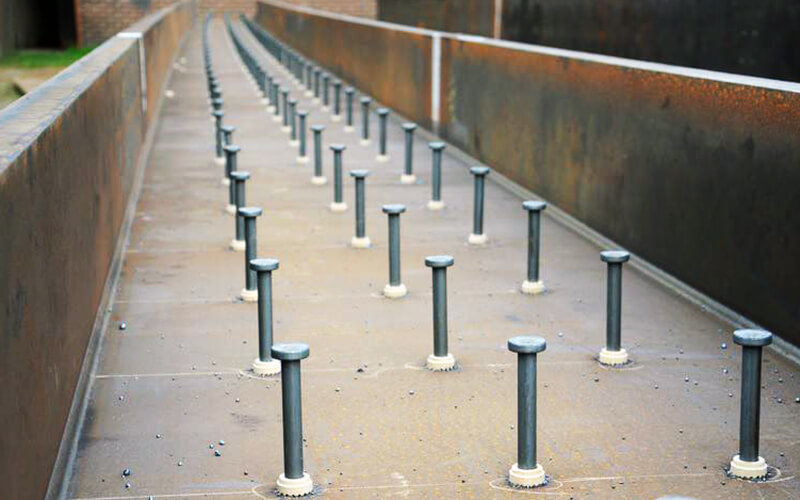
SHEAR STUDS
Shear studs are connectors used mainly in steel-concrete composite structures, aimed at creating a collaborate effect between the two materials, through the stud’s head, which is has a larger diameter than the stem.
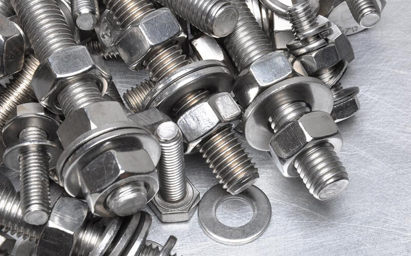
BOLTS
Elementi di giunzione smontabile, formato solitamente da un elemento maschio (vite), da un elemento femmina (dado) e da una o più rondelle, utilizzate per migliorare il bloccaggio e distribuire il carico di serraggio su una superficie più estesa.
PAINT
Considering the surface of the structure and the natural environment in which it is installed, the required quantity is calculated and supplied.


Pre-production activities consist in the realization of the single elements composing the structure through CNC machines - Computer Numerical Control.
2.1 Inbound logistic and nesting
Raw material is delivered to the production plant, sorted according to production priorities in the storage area and transported to the processing bays with the aid of magnetic supports.
The process starts with an analysis of the cutting plan or nesting, aimed to optimize the cutting of the metal sheets minimizing scrap material or production waste according to the drawings produced by the technical office: the nesting stores the data of each element such as dimensions, thickness and required processes to perform.
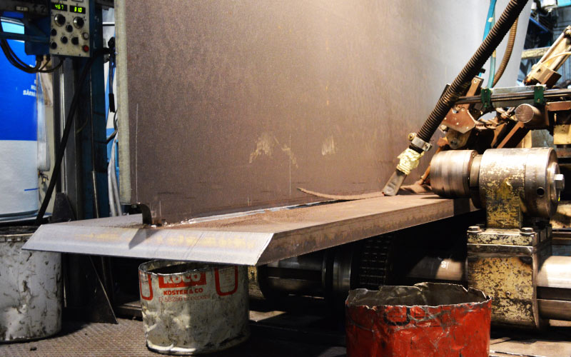
2.2 Cutting
Once the cutting plan is determined, the effective cutting phase begins on metal sheets, pipes, and angles.
In case of plasma cutting, the cutting is made through a jet of ionized gas with a temperature above 20.000°C melting the material along the way.
Generally, the cutting thicknesses are limited, therefore the cutting is faster and limits the heating of the steel, with a consequent lower thermal deformation.
In case of oxyfuel cutting or autogenous cutting, the combination of gas, propane and oxygen brings the steel to a higher temperature volatilizing the carbon and creating the cut.
It generally allows to cut greater thicknesses (up to 600 mm) and, while moving at a slower pace, it produces a more precise result even though the material is exposed to a longer heating.
During or after the cutting, according to the type of machine, the marking is executed, namely a low stress punching (with less impact on the sheets to avoid weak spots and cracks) on the cut sheet with the identification number of every single element, allowing its identification and traceability at every step of the construction.
2.3 Chamfering
When single elements are joined by welding, to ensure its correct execution, the edges of the plates are prepared through chamfering, an angled cut creating a space between once pulled together with the other element to weld called chamfer.
This space ease the deposit of the filling metal by means of molten metal during welding.
The weld joint can have different types: "V", "U", "Double U", "X" and "Y".
2.4 Drilling
When the single elements are later joined through bolting or bars, they are prepared with holes to accommodate the bolt.
Drilling is a mechanical operation removing metal swarf leaving the whole and, in case of oval and non-circular holes, it is necessary to employ a boring machine that, thanks to a rotational motion, increases the diameter of the hole and produces the desired oval shape.
2.5 Welded beams
When the size of commercial profiles exceeds the standard, the Double T beams are composed of metal sheets and large plates with a thickness usually greater than 12 mm, then welded together through automatic welding systems.
In this way it is possible to obtain section of shapes and dimensions otherwise unattainable through regular hot rolling.
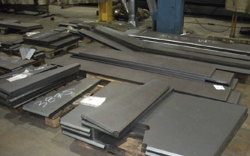
2.6 Steel preparation
If the structure needs to be coated, the material undergoes the steel preparation phase - edge grinding, corner sharpening, hole boring, all activities performed automatically to guarantee the quality - with the aim of refining the cut after pre-processing activities to ease the adherence of the paint that will be applied later on, especially in those areas of the structures such as holes and corners where rust is more likely to develop.
Through the manufacturing process, single plates are assembled in marks, namely composed elements formed by different parts.
3.1 Internal logistic
Pre-processed single elements completed during the previous phase are sorted and transported to other production plants to be assembled and manufactured into composite structures.
3.2 Assembling
To begin the composition of the elements, individual elements of the structure are temporary assembled together and fixed in position with a spot welding through electrodes/wire, allowing the subsequent jointing of the pieces until complete welding.
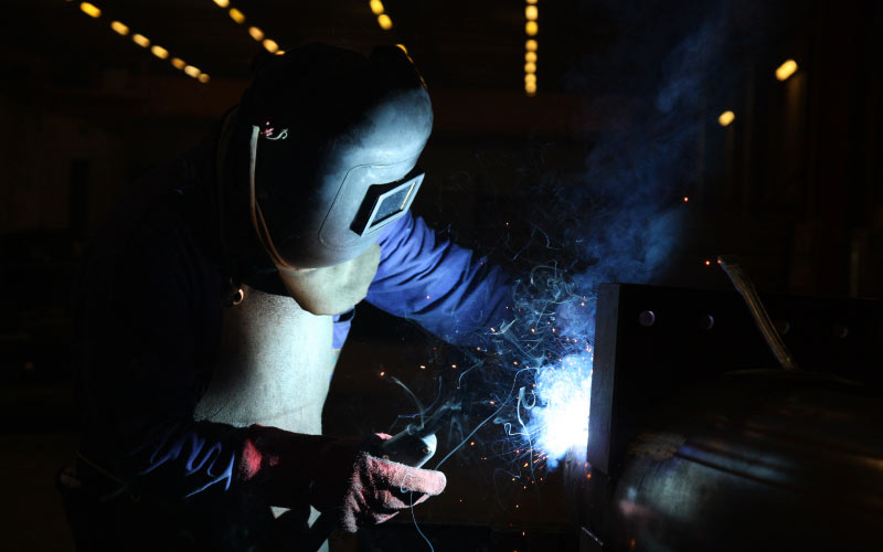
3.3 Welding
The welding process allows to joint two or more elements together with solution of continuity (namely it transfers the characteristics of the materials from on element to the other, giving continuity) by either melting part of the elements together or by merging together the edges of the elements by mean of a filler metal (welding wire).
In case of automatic welding, the filler material is applied through special machineries and it is especially recommended when the welding occurs for long regular sections without interruption.
In other cases, manual welding is preferred, and the filler material is applied by a welder who manually adjusts the welding machine and operates the heath source, adapting to the shape of the element to weld. Based on the position of the joint with respect to the operator, different welding positions can be identified: flat, horizontal, overhead, vertical, and inclined.
The type of welding can also be identified according to the thermal source creating the heat used to melt the filling metal.
In gas welding, the protection of the weld pool is ensured by a covering gas protecting the welding from the surrounding atmosphere, while in the case of arc welding, the fusion occurs through an electric “arc” that is generated between an electrode and the part to be welded, melting the electrode and laying down the filling material along the joint.
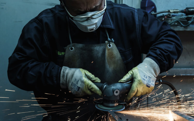
By means of a grinding wheel or grinder, at the end of the welding process, grinding may be necessary to smooth, round, polish the excess welding or to level the profile of the joined parts.
3.4 Shear stud welding
Shear studs are welded on steel beams through a pressure welding system: performed with a gun, shear stud welding is carried out by striking an electric arc between the tip of the stud and the surface of the metal element.
It is mainly employed in steel-concrete composite structures of bridges to create a collaborate effect between the two materials through the shear stud’s head.

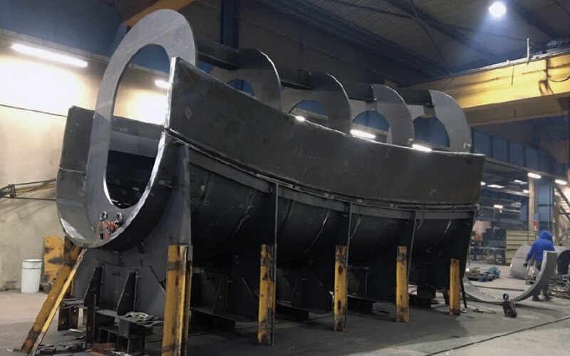
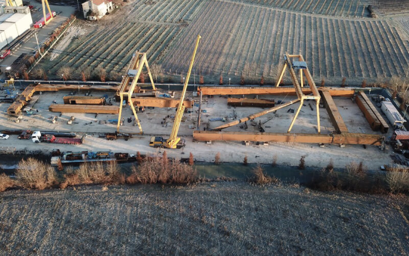
3.5 Pre-assembly
Basing on the assembly drawings, different parts of the structure are temporarily pre-assembled together.
This activity is usually carried out in the factory when the structure is particularly complex and the whole geometry needs to be checked before dispatchment to the construction site because, in this way, geometry problems can be anticipated and rectified to limit unexpected setbacks on site, allowing for a better performance and for a containment of the costs.
Surface treatment aims to prevent rust and corrosion, depending on the type of project, on its use and on the atmospheric conditions to which the structure is exposed.
4.1 Coating
The coating process consists in the application of several layers of paint on the surface of the structure to form a protective coating, whose thickness is measured in microns.
Coating usually involves the following steps:
Sandblasting: a mechanical process of abrasion of the surface through a jet of grit and air to remove the calamine (the oxide deriving from the cutting of the metal sheets) and other impurities by eroding the most superficial part of the material, obtaining the necessary coarseness to ensure a more effective paint adhesion and grip. When the elements to sandblast exceed the dimensions of the automatic sandblaster, or in case of specific evaluation, the process is carried out manually.
Application: within a few hours from the sandblasting it is necessary to proceed with the application of the paint to prevent the comeback of the oxidation process. Surfaces on composed elements might be extremely variegated and irregular, hence the painting process is preferably manual by mean of compressed air guns rather than automatic, when all the corners could be reached. The thickness of the painting is established beforehand in the technical specifications by the technical office, the quality department, and the Client, determining it according to the structure’s surface, on the corrosion level in the environment.
Intumescent: if required, a layer of intumescent paint can be applied to the structure which, at high temperatures, provides further protection against fire through an expansion process of the chemical components of the paint itself, creating a highly insulating and heat-resistant microcellular layer. Intumescent paint is the final layer, hence it is applied on site after installation is completed with particular airless pumps, with a thickness suitable to provide an R-REI fire resistance varying from 30 to 120 minutes, allowing the necessary time to evacuate the area in case of blaze.
4.2 Galvanization
The galvanization process consists in the application of a zinc coat to the steel structure to protect it from corrosion.
First, the material must adequately be prepared by pre-degreasing, pickling and final degreasing.
Second, the galvanization could be either hot-dipped galvanization (the element to be treated is completely immersed in fused zinc at a temperature of about 445°C), or through electrolytic galvanization (the element is immersed in an electrolytic solution, containing zinc salts).
4.3 CorTen
In this case, steel protection naturally occurs through its own passivating characteristic, for which the material develops a self-protecting rust layer.
This feature is specific of a kind of steel called CorTen, term originated from the abbreviation of the English terms defining the main characteristics of the material: CORrosion resistance and TENsile strength.
This option is usually not recommended in marine environments because they prevent the formation of the self-protecting coat.
4.4 Outbound logistic
Once the manufacturing and treatment are completed, finished elements are transported to the destination site to be assembled and installed in their final arrangement.
Depending on the distance and accessibility of the site, transportation can be:
By land: by means of standard trucks with a trailer of 13.50 meters or in case measures or weight limits are exceeded, specific permits are required categorizing the transport as exceptional.
By sea: intermodal transport in which the material is initially transferred by land to the port of dispatchment, to continue the route by sea in standard 40-foot containers (11.90x2.30x2.30 meters net of load) or, when the items to ship exceed this dimension and cannot fit in a container by “break-bulk”, an exceptional transportation mode with no feasibility limits allowing to load considerably large elements. Once the vessel reaches the port of destination, the material is unloaded on a truck to be taken to the construction site by land.
Airfreight: in exceptional cases, only for single lightweight elements, it is possible to rely on air shipment.
The set of all actions, processes, and documents along the entire production cycle guaranteeing the compliance of the work according with the standards and with project’s requirements.
5.1 Traceability
The entire production process complies with current quality standards to ensure materials traceability and related processes throughout the whole supply chain.
This is needed to prove the conformity of the structure, ensuring the compliance with the regulations along the different stages.
In addition to the raw material certificates to be requested from the supplier on purchase, which certify the compliance of the supply with the order based on specific sample checks, subsequent processing activities are also monitored and certified according to the project specifications.

5.2 Welding inspection
To verify that there are no impurities inside the welds, checks are carried out on the welded joints.
There are different methodologies of Non-Destructive Testing (NDT), and reference standards for each project establish the level of control to be guaranteed.
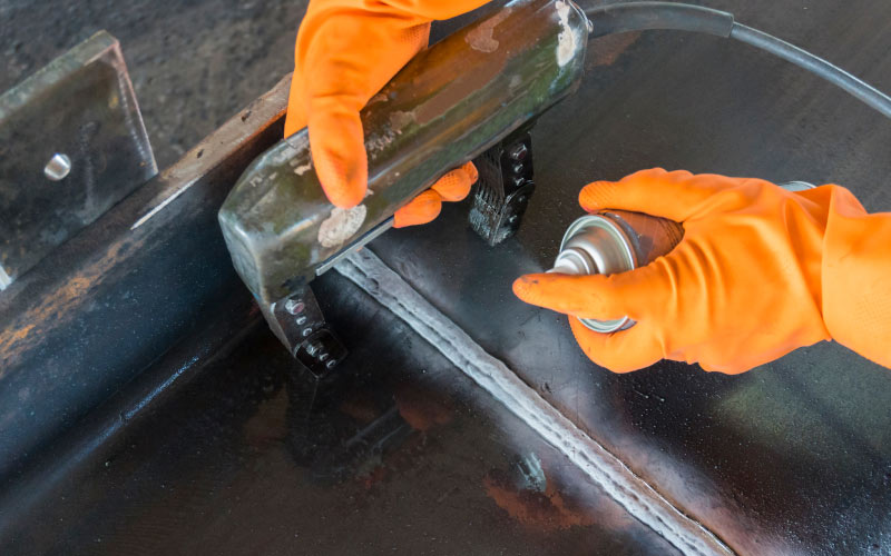
Visual inspection: it verifies the compliance of the weld with the geometric specification of the project to identify possible distortions or evident irregularities such as cracks, porosity, incomplete castings, and other visible defects.
Magnetic testing (MT): the weld is then is sprinkled with magnetic powders and then, by using a spray containing metal particles creating a magnetic field, it is possible to check if a higher concentration of metal powder appears, corresponding to the presence of defects.
This type of inspection is performed on corner welds.
Ultrasonic testing (UT): using a probe, high frequency sound waves are radiated through the material to be examined, highlighting superficial and internal defects, measuring the thickness of the materials as well as the position and the size of the defects.
This type of inspection is performed on full penetration welds.
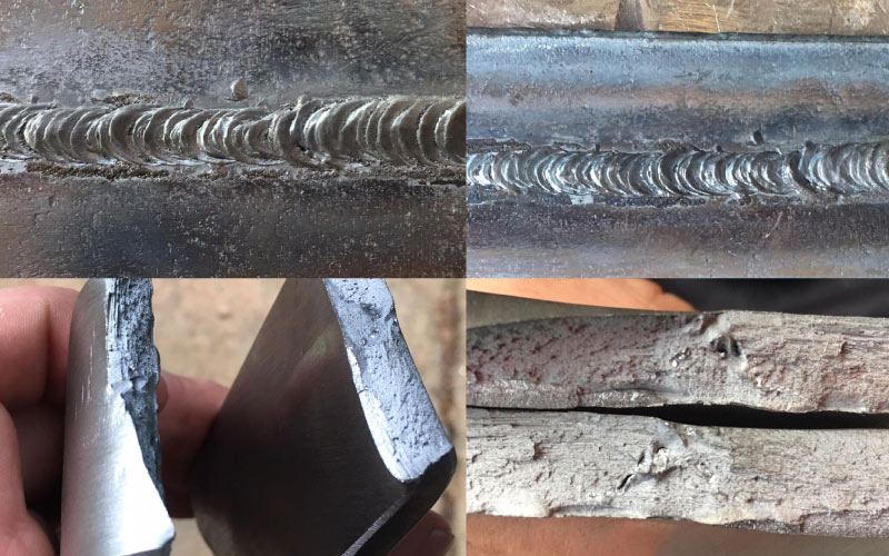
On the contrary, destructive tests involve the destruction of the joint and therefore they require the production of specific test samples.
The aim is mainly to evaluate the mechanical (tensile, bend and resilience tests) or metallurgic (macrographs or micrographs) characteristics of that typology of joint.
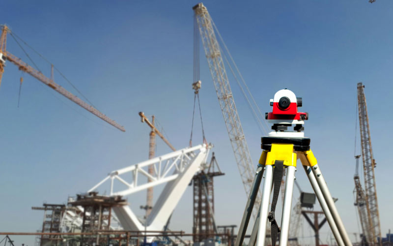
5.3 Topographic inspection
A topographic survey consists in the acquisition of the measurements and data in the space to obtain a graphic representation of the surveyed element.
During the assembly of singe elements in complex structures, it is necessary to ensure the correct geometry and position before proceeding with welding and bolting.
Topographic inspection allows to detect the coordinates of the real structure and to compare it with the model, verifying any deviations to be rectified safeguarding the right geometry.
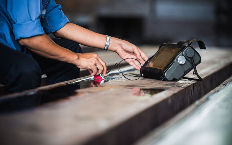
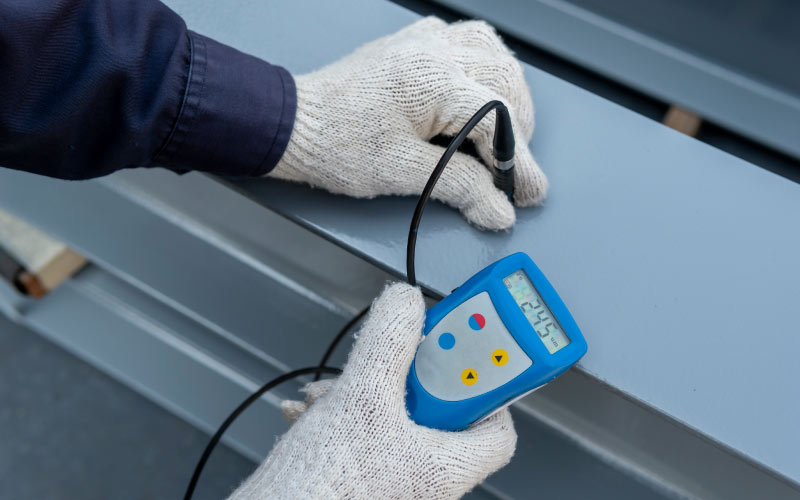
5.4 Coating inspection
Magnetic micro-tests are performed to verify the proper application of the paint and the right thickness (measured in microns), as well as to provide a warranty of the durability and tightness of the paint.
The magnetic micro-tests can measure the distance between the surface and the underlying layer of steel.
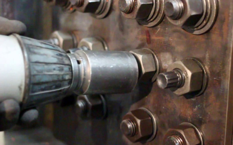
5.5 Bolting inspection
To ensure the functioning of a bolted union, bolts must be accurately tightened with a torque wrench: for obvious reasons they must not be tightened slightly,
but neither too tightly, to avoid the risk of yielding or even the breaking of the screw.
ISO 9001:2015
WORLDWIDE
Design, fabrication and installation of steel structures
ISO 1090-1/2
WORLDWIDE
Conformity of the production process for steel structures

ISO 3834
WORLDWIDE
Welding, joining and cutting for steel structures

EURO SOA
ITALY
Qualification to participate to public projects

RFI - SQ008 TMF-001
ITALY
Railway steel structures according to Italian standards

AFER
ROMANIA
Railway steel structures according to Romanian standards

RVS-15.05.11
AUSTRIA
Workshop’s painting system according to Austrian standards

ČSN EN 1090-2
CZECH REPUBLIC
Design, fabrication and installation of steel structures
CREDITS
Photograph of the Brooklyn Bridge whilst under construction - World History Archive
Brooklyn Bridge and Manhattan skyline - Detroit Publishing Company
View from Crissy Field in the Presidio of the construction of the Golden Gate Bridge with the roadbed being installed - Underwood Archives/Getty Images
Living model illustrating principle of the Forth Bridge - Wikipedia
Forth Bridge - A London Inheritance
The Statue of Liberty during construction - Horace Abrahams/Getty
Construction of the Eiffel Tower - Roger Viollet/Contributor/Getty
The Woodroot brothers and their shawl collared sweaters - Property of the Auburn University Libraries
PARTNER