Building a bridge has always exemplified man's ambition to overcome an obstacle, his tenacity and inexhaustible curiosity about the world.
Over the time, ingenuity and technology have evolved amazingly, and today increasingly ambitious challenges are matched by unprecedented engineering solutions and techniques.
Based on the mechanisms of resistance to gravitational and horizontal loads, bridges can be classified according to static scheme. Let's find out about them in this new journal.

A cable-stayed bridge is a bridge whose deck is supported by a system of cables, called stays, anchored to one or more support towers. The cables are the characterizing element of this type of bridge, and they play a key role as they bear the longitudinal bending of the deck, deferring its suspension load to the towers to which the cables are attached.
The stays are small-diameter elastic steel supports placed at regular distances in the deck, between 6 and 15 meters: however, this distance can decrease from the tower to the central part of the deck so that the forces do not differ between one stay and another.
The optimal inclination of the stays is established at 45° but can vary between 25° and 65°. As the inclination increases, the tension and linearity decrease, as do the stresses on the deck.

It is clear, therefore, that the height of the tower to which the stays are anchored has a major influence on the stiffness of the structural system: not only an architectural aspect, therefore, but also a structural one. Generally, the height of the tower is directly proportional to the length of the deck multiplied by the tangent of 25°. As for the structural scheme of cable-stayed bridges, this can be of two types, defined by the geometric arrangement of the stays: fan-shaped or harp-shaped.

Historically in use for bridges with spans between 200 and 400 meters, today cable-stayed bridges challenge the length record of suspension bridges, the only ones used for bridges with large spans. This is because with contemporary engineering techniques, cable-stayed bridges, compared to suspension bridges, are less deformable and less prone to aeroelastic instability and can therefore reach large spans up to 1,000 meters.
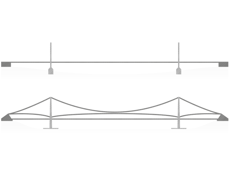
The suspension bridge is characterized by a suspension system consisting of two elements: supporting cables and hangers. The former represents the main element: they are wire ropes arranged in a curvilinear configuration, usually parabolic, from which the deck is hung by means of the hangers, hence vertical or inclined ropes.
The load-bearing cables are supported by the towers and anchored to the ground at either end of the bridge, or, in rare cases, anchored directly to the deck. The two anchor blocks, usually made of concrete, are responsible for balancing the tensile component of the cables, especially in large bridges.
As for the deck, this usually has a solid-walled box configuration, the so-called "box" deck, and is made of steel. It has a thin box section, usually between one three hundredth and one four hundredth of the span. It has torsional stiffness to avoid aerodynamic buckling phenomena.

Depending on the obstacle they have to overcome, bridges can be identified as viaducts when they cross natural obstacles (wide valleys or flat expanses), or, in urban contexts, when they pass buildings and other infrastructure located at different levels, such as elevated elevations, underground or railway lines.
Structurally, viaducts consist of a continuous series of numerous spans, which can easily reach 150 meters in height, with a structure that can be either arched or trussed. The cross-sections of the viaducts are box-shaped, single, or multi-cellular, with walls of varying thickness.
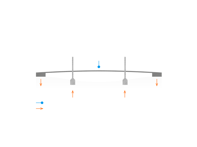
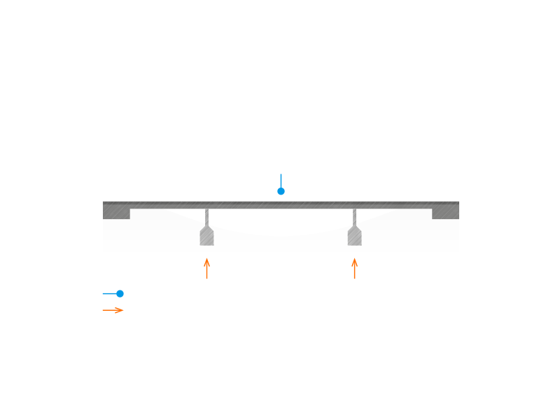
Given the considerable height that piers can reach, it is necessary to consider possible instability phenomena during the design phase. Hence the problem of assessing the tensional and deformation state of the highest piers, both for their correct utilization and for an evaluation of their ultimate resistant capacity; in the latter case, it is important to consider the resistance patterns mobilized when the displacements of the pier exceed the maximum working displacements. It is therefore important to consider the static scheme of the deck on the piers, which may be of two types: with beams in simple support or with continuous trusses.
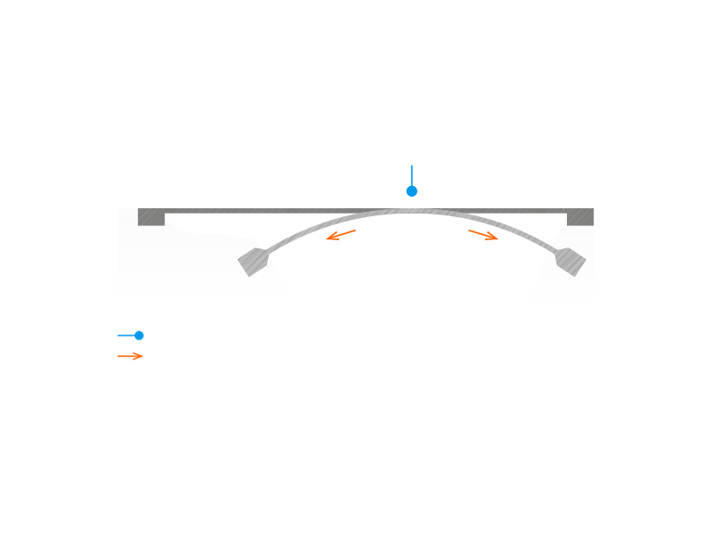
Arch bridges are characterized by the presence of a curved semi-circular shape, the arch, supporting the deck. The arch is a structural element that is constrained and shaped so that the loads exerted generate mainly compressive stresses on it: this solution reduces bending moments to negligible values compared to what a beam of the same span would do.
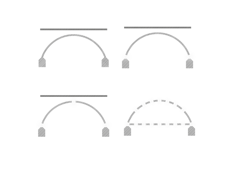
According to the degree of hyperstaticity, arch bridges can be classified into four different types.
Deck arch bridges, in which the line of pressures has no obligatory crossing points and parallel, vertical ribs connect the arch to the deck.
Two-hinged arch bridges, where the arch exerts less thrust than the interlocked arch and is connected to the deck with isolated elements, most often connected with transverse elements to form a truss structure.
Three-hinged arch bridges: here the line of pressures passes forcibly through the pins of the impost hinges and that of the keyed hinge.
With through arch bridges, on the other hand, vertical elements transmit loads from the deck to the arch: the deck absorbs the horizontal thrust of the arch and is made of steel because it is subject to high tensile stresses.
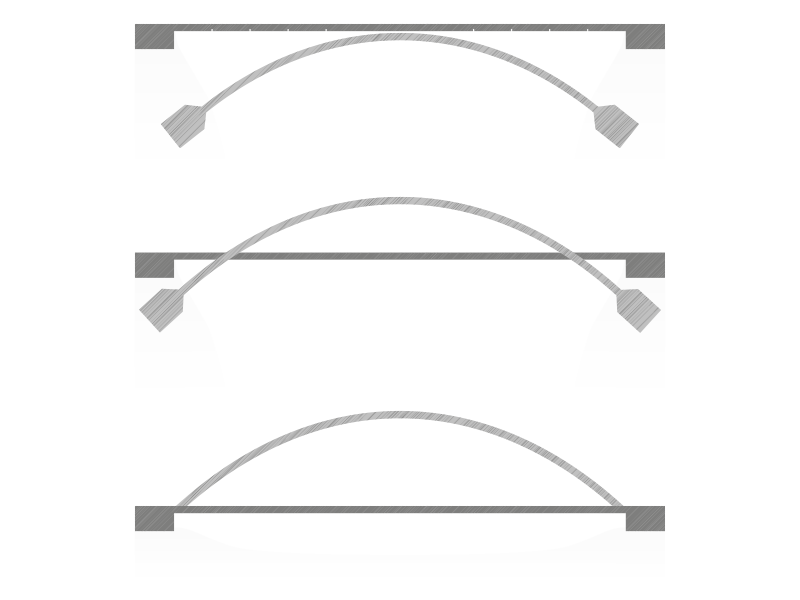
According to the position of the deck, on the other hand, from a morphological point of view arch bridges can be subdivided into upper-arch bridges, a solution generally used for reinforced concrete bridges; intermediate-arch bridges, where the arch, in order not to encroach on the carriageway, consists of a central element or splits into two lateral elements; and lower-arch bridges, built mainly in steel.
In the latter case, the deck is maintained at the height of the arch supports, and the horizontal reaction is entrusted to the deck itself, which acts as a real tie rod.
There are three main methods by which arch bridges can be built.
By means centring: this is the method most used in the past and involves an auxiliary structure or framework on top of which the segments are supported. Today it is the least favored technique, partly because of the unsustainable cost of the framwork.
By successive cantilevers: today this is the most widely used method, especially for bridges with large spans, involving the construction of the two symmetrical half-arches by successive cantilevers until the arch is locked. Due to the stresses in this phase, it is also necessary to use temporary tie rods.
By rotation of the two semi-arches which are built around the hinges using the thrust of a horizontal jack in the first phase, and finally a cable system, until the two semi-arches reach their final position.
Inclined-legs bridges present the static scheme of frame bridges, namely those bridges formed by bending-resistant connections called frame stringers and by vertical structures with a bearing function, stressed in compression, called frame uprights or piers.
When legs are inclined with respect to the vertical, for example to build viaducts crossing high valleys, the structural scheme is called indeed inclined-legs bridge, where a compression mechanism is generated on the frame stringer.
Generally, inclined-legs bridges have an intermediate behavior between that of arch bridges and frame bridges.
Inclined-legs bridges can be either simple inclined-legs bridges, in which a compression-resistant mechanism is created in the central part, or inclined-legs bridges with tie-rods, in which lateral tie-rods are inserted to reduce the positive moment.
CREDITS
e-nsight.com
teknoring.com
promozioneacciaio.it
ordineingegnerimantova.it
ingegneriastrutturale.net
Prof. Pier Paolo Rossi, Ponti e grandi strutture (lezione), Università degli studi di Catania
Prof. Domenico Raffaele, Classificazioni tipologiche (lezione aa. 2019-2020), Politecnico di Bari
PARTNER